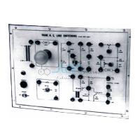
Single-Phase Half-Controlled Bridge Converter

Product Code : JA-PET-1431
The Single-Phase Half-Controlled Bridge Converter is a power electronics trainer for the symmetrical and the asymmetrical half-controlled bridge. Two SCRs are fired through 1:1 pulse transformers from an on-board firing circuit, and a 40 W bulb is the load. Students set the firing angle and watch the waveforms on an oscilloscope. A 230 V, 200 mA isolation transformer protects instruments that are not isolated.
Specifications of the half-controlled bridge converter board
| Product | Single-Phase Half-Controlled Bridge Converter |
|---|---|
| Product code | JA-PET-1431 |
| Configurations | Symmetrical and asymmetrical single-phase half-controlled bridge |
| Power devices and gate drive | Two SCRs, fired through two 1:1 pulse transformers |
| Firing electronics | Two op-amps; quad Ex-OR, triple 3-input AND, hex inverter and quad 2-input AND gate ICs; three NPN transistors; potentiometer for the reference voltage |
| Supplies on the board | 6 V AC at 100 mA; ±12 V DC at 100 mA, fixed regulated ICs |
| Isolation transformer | 230 V AC at 200 mA; protects external instruments that are not isolated |
| Load and mains | 40 W bulb load; mains 230 V ±10%, 50 Hz AC with ON/OFF switch, fuse and jewel light |
| Size and weight | W 412 x H 150 x D 310 mm; about 7 kg |
| Accessories and other apparatus | 4 mm stackable spring-loaded patch cords, 0.5 m, and operating instructions; a dual-trace 20 MHz oscilloscope is also needed |
| Manufacturer | JaincoLab, Ambala, India |
Converter experiments on the half-controlled bridge board
- Symmetrical bridge. Wire the symmetrical configuration with the 40 W bulb as the load. Set several firing angles with the reference potentiometer and record the load voltage on the 20 MHz Dual Trace Cathode Ray Oscilloscope at each one.
- Asymmetrical bridge. Rewire the board for the asymmetrical configuration and repeat the readings. Compare when each SCR conducts with the symmetrical case.
- Firing pulses. View the gate pulses after the pulse transformers and relate their position to the firing angle. Compare the method with the Firing Circuit Using Ramp Comparator Scheme board.
- Half against fully controlled. Repeat a run on the Single Phase Fully Controlled Bridge Converter and compare the two outputs at the same firing angles.
Frequently Asked Questions
What is the difference between the symmetrical and the asymmetrical half-controlled bridge?
Both use two SCRs and two diodes and give the same output for a given firing angle. In the symmetrical bridge the SCRs share a common cathode, so the load current freewheels through an SCR and a diode. In the asymmetrical bridge the SCRs sit in one leg and the diodes in the other. The two diodes then carry the freewheeling current, and each SCR switches off sooner.
Can a half-controlled bridge feed power back to the supply as an inverter?
No. The freewheeling path through the diodes stops the output voltage going negative. The bridge therefore works in one quadrant only, and power flows from the AC supply to the load. Inverter operation needs a fully controlled bridge, in which all four devices are SCRs.
Why does the bulb dim as the firing angle is increased?
Each SCR is fired later in its half cycle, so a smaller part of every half cycle reaches the bulb. The average and RMS output both fall, and the bulb dims. At small firing angles the bulb is close to full brightness, and near the end of the half cycle it is almost dark.
How should the oscilloscope be connected to see the converter waveforms?
Run the board through its isolation transformer and keep the oscilloscope earthed in the normal way. Use one common reference point for both probe grounds, or differential probes for points at different potentials. Never clip a ground lead onto a live node, and set the scope inputs before switching the board on.
What comes with the half-controlled converter board?
The board comes with its 230 V, 200 mA isolation transformer, a 40 W bulb load, 4 mm patch cords and operating instructions. It needs 230 V, 50 Hz mains and a dual-trace 20 MHz oscilloscope. The related firing circuit and fully controlled converter boards can be quoted in the same enquiry.
How are the SCR gate pulses generated and isolated on the board?
A firing circuit of two op-amps, logic gate ICs and three NPN transistors sets the firing angle from the reference potentiometer. Each pulse reaches its SCR through a 1:1 pulse transformer, which keeps the low-voltage firing circuit apart from the power circuit.
Other SCR converter trainers in the range
- Single Phase Fully Controlled Bridge Converter
- Three Phase Half Controlled Thyristorized Bridge Converter
- SCR Converters and Reactive Loads
- Firing Circuit Using OP AMPS And Gates
See the Power Electronics Trainers range and more electronics lab equipment from JaincoLab, an electronics lab equipment manufacturer in India.
For a quotation, send the product name and the quantity you need through our contact page. For tender or project supply, see our tenders page.